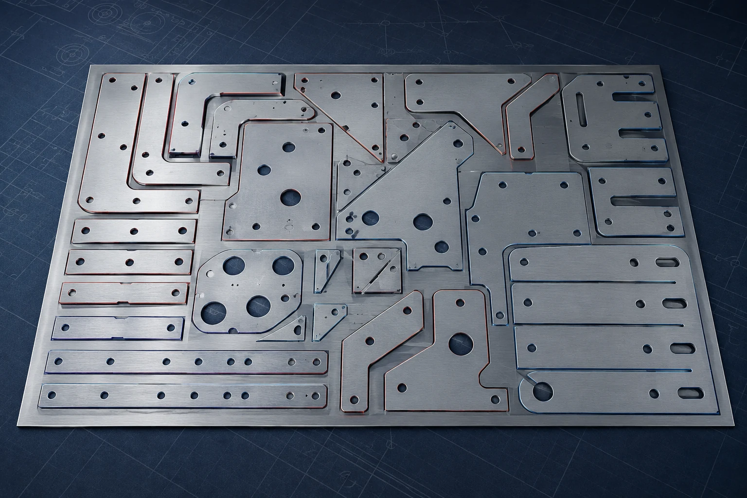
Why yield has more leverage than it looks
On most laser-cut parts, material is the largest single line in the cost, ahead of machine time. That is what makes nesting worth attention: a change that improves yield by a few percent applies to every sheet you buy for the life of the job, and it compounds across a year in a way that shaving seconds off a cycle rarely does.
But there is a trap in that logic, and it runs through this whole article. The tightest nest is not automatically the cheapest part. Yield trades against cycle time and against downstream labour, and a nest optimised for one of those three can quietly cost you more on the other two.
What utilization measures, and why a target number is unhelpful
Utilization is simply the part area divided by the sheet area. It is easy to calculate and easy to misuse.
The number you can achieve is dominated by your part geometry, not by operator skill or by which software you bought. A nest of rectangular blanks will reach figures that a nest of curved, irregular brackets never will, no matter who is driving. Comparing your utilization against a number you read somewhere tells you almost nothing, because you are not cutting the same parts.
What is useful is comparing your own jobs against themselves. Take a repeat job, record its utilization, change one thing, and measure again. That comparison is like for like, and it is the only one that reliably tells you whether a change helped.
The levers that actually move yield
Part rotation, and the constraint people forget
Letting the nester rotate parts freely improves fit, sometimes dramatically. It is also the lever most likely to create a problem downstream, and this is the one that catches shops running a laser and a press brake together — which is most shops.
Two constraints override free rotation:
- Grain direction on parts that get bent. Bending across the grain and bending along it are not equivalent. A bend running parallel to the rolling direction is more likely to crack the outer fibre, and the minimum bend radius you can safely use changes with orientation. A nester allowed to rotate freely will happily produce a beautifully packed sheet of parts that split at the brake.
- Directional finishes. On brushed or otherwise directional stainless, rotation shows. Parts that nest perfectly can be visually unusable on an assembly where the grain has to run consistently.
The fix is not to disable rotation. It is to lock it on the parts that need it and leave it free on the parts that do not, which means the person nesting has to know which is which. That is a drawing and process question, not a software one.
Common-line cutting
Where two parts share a straight edge, the cut can serve both: one pass instead of two, and one fewer pierce. It reduces cut length and pierce count together, which is why it shows up as both a material and a cycle-time gain.
The tradeoff is that the two parts become dimensionally coupled. There is no skeleton between them, so any deviation in that cut belongs to both parts, and they separate as they are cut rather than staying held in the sheet. It works best on simple straight-edged parts in the same material and thickness, and it is worth being more cautious with it on tight-tolerance work.
Part spacing is a thermal question, not only a geometric one
It is tempting to treat the gap between parts as pure waste to be minimised. It is not. Spacing also controls heat.
Packing small parts tightly means cutting repeatedly in a small area, and the heat has nowhere to go. Edge quality falls off, small features distort, and on thin material you can start burning rather than cutting. The nest that looks best on screen can produce the worst parts on the table.
Two things help: keep enough spacing for the material and thickness you are running, and sequence the cut so that consecutive cuts are not immediately adjacent. Letting the previous area cool while you cut elsewhere costs nothing in material.
Micro-joints, and what they are actually for
A micro-joint is a small uncut tab left holding a part in the skeleton. The purpose is not tidiness. It is to stop a part tipping up into the path of the cutting head, which at best costs you a nozzle and at worst does real damage.
They are not free. Every micro-joint has to be broken out and the witness mark dressed afterwards, and that is labour on every part. The judgement is where the tip-up risk is genuine — small parts, thin material, parts that fall through or sit proud of the slats — rather than applying them everywhere by default.
Keep lead-ins in the scrap
Piercing is the most violent thing the machine does to the material, and it leaves a mark. Lead-ins and pierce points belong in the skeleton, in an internal scrap area, or somewhere the finished part does not care about — not on a visible or dimensioned edge. This costs nothing to get right and is irreversible if you get it wrong.
Material yield, cycle time and downstream labour pull against each other. A tighter nest can mean more micro-joints to break out, more heat problems, and more sorting. A faster nest wastes material. Which way to lean depends on what is actually scarce in your shop — machine hours or material spend — and that is a business decision, not a software setting.
Remnants are worth more than the percentage suggests
Utilization treats all unused material identically, which is misleading. Material left as a clean rectangular remnant you can put back on the rack and cut from next week is worth real money. The same area distributed as thin skeleton webbing between parts is scrap.
A nest that scores slightly lower on utilization but leaves a usable remnant is often the better commercial outcome. This only works if remnants are actually labelled, stored and findable — otherwise they sit in a corner until somebody throws them out, and you were better off with the higher percentage.
When built-in nesting stops being enough
Hans LaserNest and CypCut both nest, and for a large number of shops that is genuinely sufficient. Buying dedicated nesting software because it sounds more professional is a good way to spend money without changing anything.
The signals that you have actually outgrown built-in nesting tend to be these:
- High part-mix volume, where nesting is a daily time cost rather than an occasional task
- Repeat production at a scale where a few percent of material is a number worth chasing
- A need to nest automatically across multiple sheets, thicknesses or materials at once
- Demand-driven nesting tied into an ERP or MRP system rather than job by job
- Remnant tracking that needs to be a managed database rather than a rack and a memory
Packages like SigmaNEST and Lantek exist for exactly this, and where the volume justifies them they pay back. The case is volume multiplied by material cost, not sophistication for its own sake. Do the arithmetic before the demo: licence and training cost against your annual material spend times the yield improvement you actually expect. If you cannot state the yield gain you are buying, you are not ready to buy it.
A practical way to start
Pick one repeat job. Record its utilization, its cycle time, and roughly how long breakout takes. Change one lever — free up rotation on the parts that allow it, or enable common-line cutting, or open the spacing if you have been fighting edge quality. Run it again and compare all three numbers, not just the utilization.
Doing that once on a real job teaches you more about your own part mix than any benchmark figure, and it tells you which of the three costs is the one actually worth attacking in your shop.