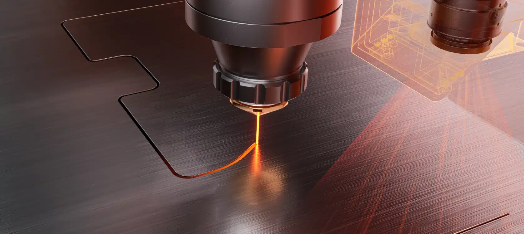
The kerf is slightly wider than the focused beam because a thin band of metal melts and vaporizes on each side. Kerf width grows with material thickness and is shaped by power, focus, assist gas, and nozzle choice.
Kerf ranges compiled by Rise Tek Machinery from fiber laser cutting data. Actual kerf varies with machine, optics, parameters, and required edge quality — treat these as reference benchmarks.
Every cutting process removes a slug of material to separate a part from the sheet. That removed width is the kerf. On a fiber laser it's narrow — a fraction of a millimetre — which is precisely why laser holds tight tolerances, cuts clean holes, and nests parts tightly to save material. Understanding kerf is the difference between parts that drop out to size and parts that come out consistently under- or over-sized.
What Kerf Actually Is
When the focused laser beam meets the metal, it heats a tiny spot to melting and vaporization temperature. The assist gas blows the molten material out of the bottom of the cut. What's left is a slot — the kerf — that is a little wider than the beam itself, because heat spreads a short distance sideways into the surrounding metal (the heat-affected zone, or HAZ).
Fiber Laser Kerf Width by Material & Thickness
Thickness is the single biggest driver of kerf width — a thicker cut needs more energy and a slightly wider channel to clear the melt. Assist gas matters too: oxygen (used on thicker mild steel) widens the kerf a little through its exothermic reaction, while nitrogen (used on stainless and aluminum) keeps it tighter. Typical fiber laser values:
| Material & Thickness | Assist Gas | Typical Kerf Width |
|---|---|---|
| Mild steel — 1 mm | Nitrogen / Air | 0.10–0.15 mm |
| Mild steel — 3 mm | Nitrogen | 0.15–0.20 mm |
| Mild steel — 6 mm | Oxygen | 0.20–0.30 mm |
| Mild steel — 10 mm | Oxygen | 0.25–0.35 mm |
| Mild steel — 20 mm | Oxygen | 0.35–0.50 mm |
| Stainless — 1 mm | Nitrogen | 0.10–0.15 mm |
| Stainless — 6 mm | Nitrogen | 0.20–0.30 mm |
| Aluminum — 3 mm | Nitrogen | 0.15–0.25 mm |
| Aluminum — 8 mm | Nitrogen | 0.30–0.45 mm |
The practical takeaway: for most sheet-metal work under 6 mm, you can plan around a kerf of roughly 0.15–0.30 mm. Your machine's technology tables give exact values per parameter set.
The 6 Factors That Control Kerf Width

Top Kerf vs Bottom Kerf: Understanding Taper
A laser cut is rarely a perfectly straight-walled slot. Because the beam converges to a focal point and then diverges, and because the assist gas loses energy as it travels down through the material, the kerf is usually slightly wider at the top than the bottom. That difference is taper.
On thin sheet, taper is usually negligible — walls are effectively square. It becomes more noticeable on thick plate. For most fabrication it doesn't matter, but for parts that stack, press-fit, or seal against a mating face, taper is worth checking. Correct focus position and gas pressure are the main levers for minimizing it.
Kerf Compensation: Why Your Parts Come Out to Size
Here's the part that trips up newcomers. The CNC follows a programmed path, but the laser removes material along that path. If the beam center traced the exact part outline, every external dimension would come out undersized by one kerf width, and every hole would come out oversized by one kerf width.
The fix is kerf compensation (kerf offset): the CAM/nesting software automatically steers the beam center off the outline by half the kerf width — to the outside of holes and the inside of the part perimeter — so the finished edge lands exactly on the drawing dimension.
Kerf compensation is only as accurate as the kerf value in your cutting parameters. If the stored kerf is wrong for the material and thickness you're running, parts drift off-dimension — holes slightly large, tabs slightly small. Keeping accurate, material-specific kerf values in your technology tables is what keeps a laser holding tolerance day after day.
Kerf Across Cutting Technologies
Kerf width is one of the clearest advantages fiber laser holds over older cutting methods. A narrower kerf means tighter tolerances, cleaner holes, less wasted material between parts, and less post-processing.
| Technology | Typical Kerf Width | Relative Taper & HAZ |
|---|---|---|
| Fiber Laser | 0.1–0.4 mm | Minimal |
| CO₂ Laser | 0.2–0.5 mm | Low |
| Waterjet | 0.8–1.2 mm | Low (no HAZ) |
| Plasma | 2–6 mm | High |
This is a major reason shops move from plasma to fiber laser: the fiber laser kerf is up to 20–30× narrower than plasma, which transforms edge quality, hole accuracy, and material yield.
Practical Tips to Control Kerf
- Use material-specific parameters. Don't reuse a 3 mm program on 10 mm plate — the kerf, focus, and gas are all different.
- Keep the cutting head and optics clean. Contaminated protective glass shifts focus and widens/destabilizes the kerf.
- Verify focus position. Focus drift is the most common cause of a kerf that suddenly runs wide or tapered.
- Match nozzle to thickness. A worn or wrong-size nozzle disrupts the gas stream and the kerf with it.
- Confirm kerf compensation values. After any parameter change, cut a test coupon and measure a known dimension before running production.
For more on the parameters behind these numbers, see our guides on choosing fiber laser power, the fiber laser cutting speed chart, and assist gas selection.