A tube-bending demonstration should prove that the proposed machine, tooling and process can make your part to agreed requirements. A smooth-looking bend or a short cycle video is useful context, but acceptance needs recorded measurements on identified samples. For Canadian buyers, the strongest comparison uses the same drawing, stock and inspection plan for each supplier.
Agree the criteria before the demonstration. This guide is a purchasing and inspection-planning checklist, not an operating procedure or a universal acceptance standard. The limits and required tests must come from the part drawing, application requirements and the responsible reviewer.
1. Freeze the trial conditions
Record the drawing revision, units, material grade and condition, tube outside dimensions, wall thickness, centreline radius, bend sequence and finished-part requirements. Identify the stock heat or batch where available. Use representative production material, including surface condition and welded or seamless construction, rather than accepting a demonstration on an easier substitute without noting the difference.
Record the machine model, control configuration, program revision and tooling set. Identify whether mandrel and wiper tooling are included. A result made with demonstration-only options does not establish the capability of a differently equipped quotation. Use the tube-bender quotation checklist to resolve missing job information first.
2. Inspect the released geometry
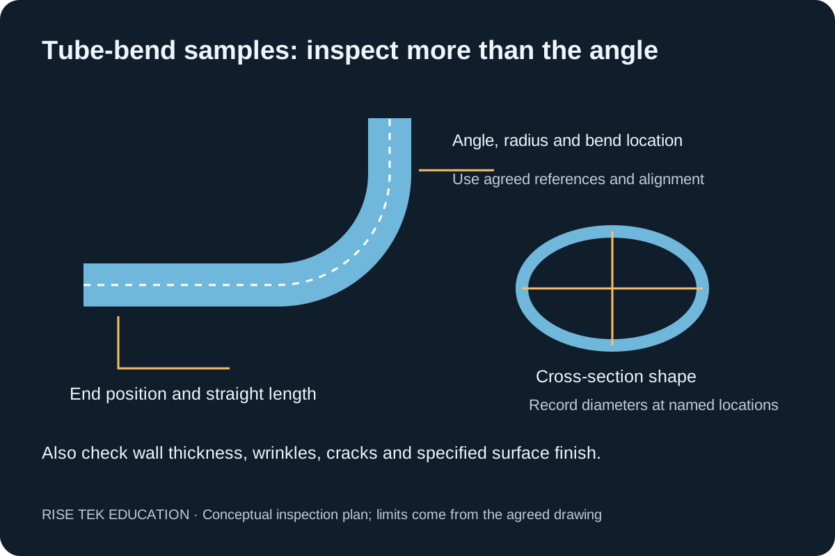
Agree the inspection stage: typically after the tube is released from the tooling, with its support condition documented. Measure the finished angle, bend location, straight lengths, end positions and orientation between bends against the drawing. State how the part is aligned to its reference features. Programmed angles and positions are not substitutes for finished-part measurements.
For three-dimensional parts, choose a method capable of resolving the required geometry. A checked fixture can test defined fit conditions; suitable coordinate or optical measurement can produce dimensional results. A fixture fit does not by itself establish wall thickness or every drawing dimension. Confirm instrument suitability, calibration status and measurement capability for the tolerance involved.
3. Separate ovality, wall and surface checks
| Check | Record | Agree in advance |
|---|---|---|
| Overall geometry | Actual angles, lengths, end positions and bend-plane orientation | Drawing references, measurement locations, tolerance and support condition |
| Cross-section / ovality | Largest and smallest outside diameters at specified sections | Sampling locations, calculation convention and permitted result |
| Remaining wall | Actual wall readings at agreed locations, including the outer bend where required | Minimum wall, measurement method and any destructive sample allowance |
| Wrinkles, flattening and cracks | Location, photographs and measurable extent where applicable | Acceptance criteria and whether additional examination is required |
| Surface condition | Clamp marks, scratches and finish at named areas | Permitted marking, finish criteria and downstream needs |
| Assembly fit | Fit against agreed references or a checked fixture | Whether clamping is permitted and which dimensions the fixture verifies |
Ovality describes a departure from a circular cross-section. If the report uses a percentage, name the formula and denominator: a percentage based on nominal OD is not interchangeable with one based on a measured reference diameter. Keep the raw diameter readings and section location so the result can be checked. Do not invent a single ovality limit for every tube application.
The outer bend wall can thin during forming. An end measurement or the nominal stock wall does not establish the minimum remaining wall through the bend. Agree an appropriate technique, access and locations before the trial; ultrasonic measurement or sectioning may be considered where suitable and agreed. A calculation is not a replacement for a required measurement.
Record visible wrinkles, flattening, cracks and tool marks separately. Surface appearance and dimensional fit answer different questions. Keep unresolved indications open for review rather than approving them because the part fits a fixture. Cosmetic marking criteria should reflect the actual application and any finishing work.
4. Check consecutive samples and a repeat setup
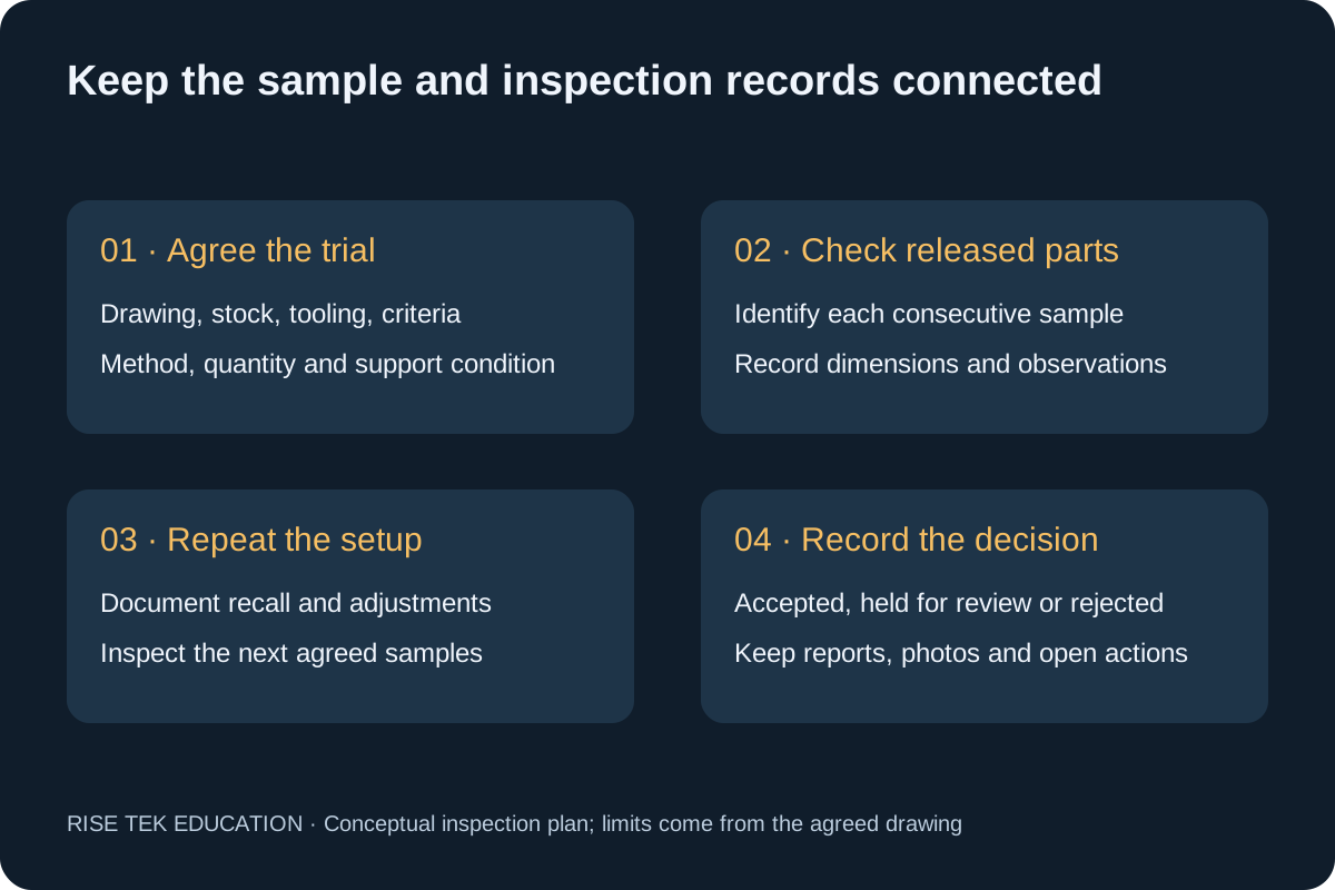
Ask for an agreed run of consecutive parts, including the first part and any rejected or reworked samples. Assign a sample ID and keep results for each part. One selected good sample does not demonstrate consistency across a run. The number of samples depends on the purpose of the trial and the agreed acceptance plan; a short demonstration does not establish long-term process capability.
For recurring jobs, include a repeat setup or program recall under an agreed procedure. Record which tooling, stops and parameters are restored and which adjustments are made before acceptance. Inspect the subsequent parts using the same method. This reveals work that is hidden when only a continuous bending cycle is timed.
To compare controls, read CNC versus NC tube benders. Automation changes which tasks are programmed; it does not remove the need to verify the finished tube.
5. Time the complete accepted-part cycle
Record setup and first-part approval separately from the repeat cycle. Include loading, positioning, bending, unloading, inspection and any rework. Keep elapsed machine-cycle time separate from operator time when tasks overlap. State whether time was measured directly or estimated.
For example, a trial with ten produced parts and eight accepted parts should report both quantities. It should not use ten as the accepted-output denominator. That example illustrates recordkeeping only; it is not a RollTek performance result or an acceptable rejection rate. No fixed throughput advantage or payback period follows from a single demonstration.
6. Keep a signed-off trial record
Save the drawing revision, stock identification, quoted configuration, tooling list, sample IDs, inspection report, photos and cycle records together. Identify the reviewer and the disposition of each result: accepted, held for review or rejected. Record any agreed corrective action and retest requirement before treating the demonstration as complete.
Download the blank tube-bend sample-acceptance worksheet. It provides fields for requirements, method, readings, decision and follow-up; it does not calculate pass/fail or supply default tolerances. Attach the agreed trial scope to the quotation and clarify what will be checked at delivery or commissioning.
Check these out
Send your drawing for a model-specific application review.
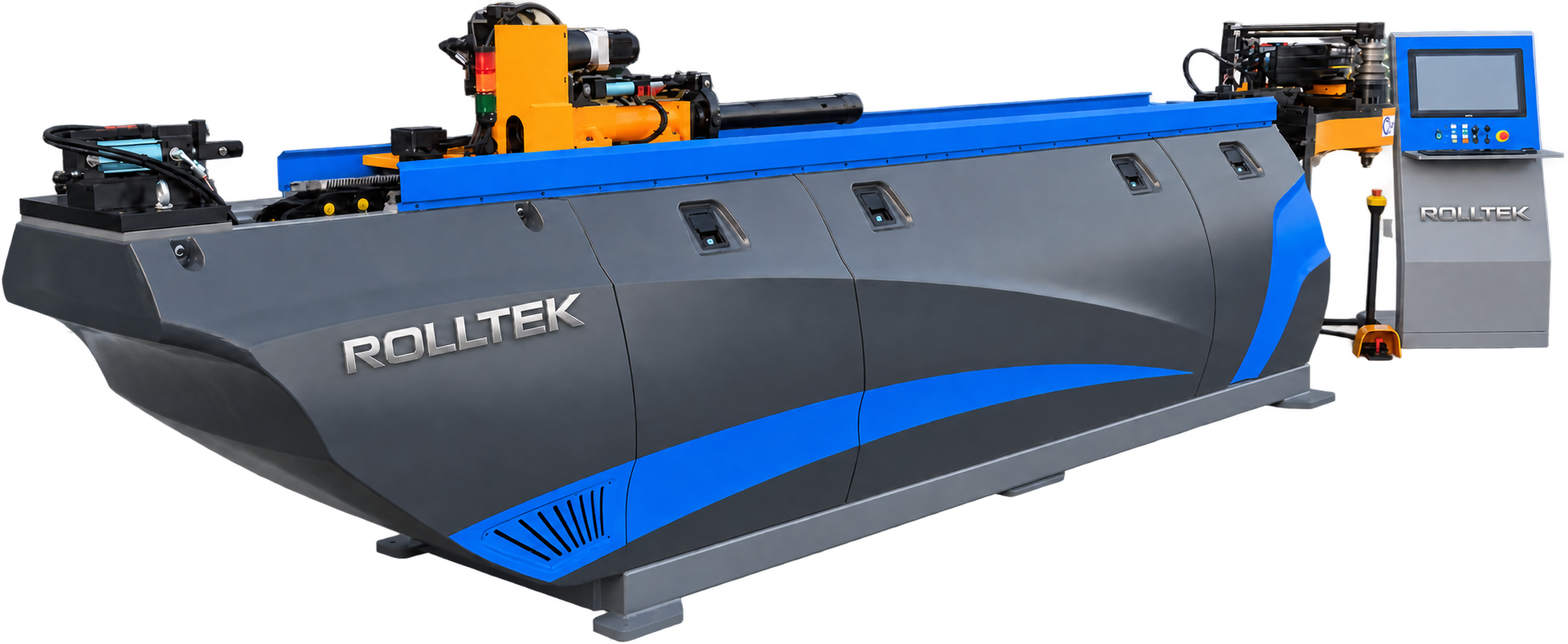
RollTek ORBIT CNC tube benders
Request a trial using your complete drawing and the quoted control and tooling configuration. Existing branding visualization; confirm final equipment appearance.
Explore machines →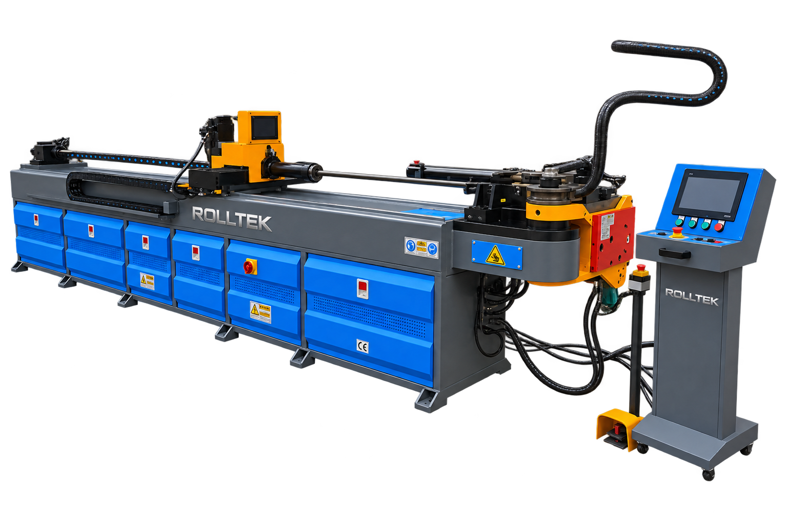
RollTek MANDRA tube benders
Review the exact model, tube specification and included mandrel tooling before agreeing sample acceptance. T51-NR branding visualization; other models differ.
Explore machines →Frequently asked questions
What should a tube-bend sample inspection include?
Agree geometry, cross-section shape, remaining wall, surface condition and assembly fit checks. Record the actual drawing limits, method, sample identity and inspection condition.
What ovality percentage is acceptable after tube bending?
There is no universal value for every application. Use the requirement approved for the part and specify the formula, reference diameter and measurement locations.
Does a good-looking bend prove the wall thickness is acceptable?
No. Appearance does not establish the remaining wall through the bend. Agree suitable measurements at the required locations and compare them with the specified minimum.
How many samples should a tube-bender trial include?
Agree the quantity and purpose before the trial. Inspect consecutive identified parts and include a repeat setup when relevant. A small demonstration does not establish long-term process capability.
Should the tube be measured while it is clamped in the bender?
Use the agreed finished-part inspection condition, normally after release with defined supports. If restrained measurements are also required, record them separately so different conditions are not confused.