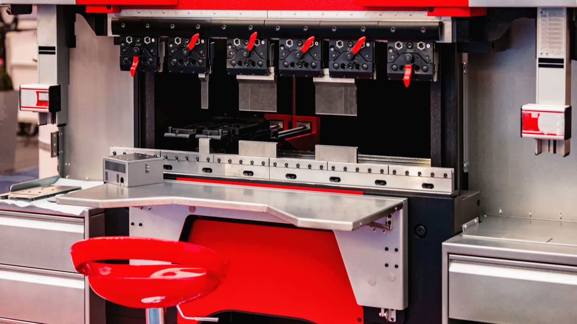
A press brake produces exactly what its tooling allows it to produce. The machine provides tonnage and precision control — but the punch profile, die opening, and tooling material determine what geometries are achievable, what inside radius the part carries, and whether a 6mm stainless flange cracks at the bend zone or comes out clean.
This guide covers everything Canadian fabricators need to understand about press brake tooling: the two major tooling standards, the full range of punch and die types, how to select the right die opening, how inside radius actually works in air bending, and the setup mistakes that shorten tooling life. If you haven't yet worked through machine sizing, start with our press brake tonnage calculation guide first.
European vs American Tooling Standards
Press brake tooling exists in two primary standards, and mixing them is not possible without adapter hardware.
European Style (Wila / Trumpf Compatible)
European-style tooling uses a precision-ground tang that seats into a quick-change safety holder on the ram. The safety holder has a locking key that retains the punch during setup — preventing accidental drops. Tools are sold in shorter segments (typically 100mm, 200mm, 300mm, and 415mm) that combine to cover the full bed length, with gaps left intentionally where needed for part clearance.
Dener and Haco EuroMaster S press brakes both ship with European-style quick-change holders as standard. This is the predominant tooling standard for CNC press brakes purchased in Canada in the past 15 years.
American Style (Promecam / Wilson)
American tooling uses a heavier T-slot mounting system, typically with longer individual segments. It is widely found in North American job shops on older machines and import press brakes that entered the market before European tooling became dominant here. Adapters exist to run European-profile punches in American holders, but they add height and require verifying die clearance and maximum throat depth.
Before purchasing additional tooling, confirm whether your machine uses European or American holders, and note the tang height. European holders come in several tang heights (1V, 2V, 3V etc.) and punches must match. Your machine manual or the tooling supplier can confirm the correct specification.
Punch Types
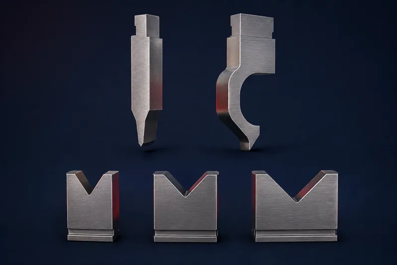
The punch is the upper tool — it moves with the ram and applies force to the material. The profile of the punch determines what bend geometries are achievable and how much clearance exists around the part during forming.
Standard Straight (85° / 88°)
The workhorse punch for general-purpose bending. A straight-body design with a small tip radius. Suits all standard V-die air bending on flat sheet. The 85° or 88° included angle gives slight clearance past 90° for springback compensation.
Acute Angle (30°, 45°, 60°)
A narrow-profile punch for sharp angles, Z-bends, and applications requiring an included punch angle smaller than the part angle. Concentrates force at a smaller contact area — more demanding on tooling material at high tonnage.
Gooseneck (Swan-Neck / Offset)
The punch shank offsets laterally from the tip, creating clearance for already-formed flanges to pass alongside the tool body. Essential for bending subsequent flanges on deep boxes and pans. The offset depth determines the maximum box height it clears.
Hemming / Flattening
A flat-face punch used in the second stroke of a hem bend — pressing the pre-bent acute flange flat against the parent sheet. Used with a hemming die for enclosure panels, HVAC ductwork, and safety edges.
Offset / Z-Punch
Produces a Z-bend or step in a single stroke. The punch geometry simultaneously forms two opposite-direction bends. Common for brackets, chassis offsets, and stepped flanges. Requires a matched offset die.
Large Radius / Parabolic
A punch with a large tip radius for forming curved profiles rather than sharp bends. Used for roller-bend style forming of large-radius parts when a rolling machine is not available. Multiple air-bend hits are taken across the part.
Die Types
The die is the lower tool — it provides the opening the material bends into. The die opening width is the single most important tooling selection decision, as it controls both required tonnage and the inside radius of the finished bend.
Single V-Die
One V-opening per die block. The most common die type. Each die covers one material thickness range. Select die opening = 8× material thickness for air bending. Matched sets cover a range from 6mm to 120mm openings.
Double V-Die
Two V-openings on one die block — e.g., 32mm on one side and 48mm on the other. Flip the die to switch between two common thicknesses without changing tooling. Standard in job shops with two or three dominant material gauges.
Multi-V (Rotating / 4-Way)
Three or four V-openings on a single rotating block. Fastest setup time for shops running mixed gauges throughout the day. Slightly more mass to handle but eliminates most die changes between jobs.
Channel Die (U-Die)
A flat-bottomed opening that forms U-profiles, channels, and square-bottom trays in a single stroke. Common for cable tray, electrical enclosures, and structural structural shapes. Requires a matching channel punch.
Hemming Die (Acute Die)
A flat top surface used in the second stroke of a hem bend. The pre-bent flange is folded flat against this surface. Often supplied as a flat-top segment that mounts in the standard die holder.
Radius / Curving Die
A die with curved edges rather than sharp V-shoulders for forming large-radius bends without sharp shoulder marks on the material surface. Used on visible cosmetic surfaces or anodized aluminum where die marks are unacceptable.
Die Opening Selection and the Inside Radius Rule
The die opening is the most consequential tooling decision at setup. It controls three things simultaneously: the tonnage required to bend, the inside radius produced, and the minimum flange length achievable.
The 8× Rule for Die Opening
For air bending mild steel up to 10mm thick, the standard starting point is V = 8 × material thickness. This produces a workable inside radius, keeps tonnage within practical limits, and avoids surface marking from the die shoulders contacting the part face.
| Material Thickness | Standard Die Opening (8×) | Resulting Inside Radius | Min Flange Length |
|---|---|---|---|
| 1 mm | 8 mm | ~1.2–1.6 mm | ~6 mm |
| 2 mm | 16 mm | ~2.4–3.2 mm | ~12 mm |
| 3 mm | 24 mm | ~3.6–4.8 mm | ~18 mm |
| 4 mm | 32 mm | ~4.8–6.4 mm | ~24 mm |
| 5 mm | 40 mm | ~6–8 mm | ~30 mm |
| 6 mm | 48 mm | ~7.2–9.6 mm | ~36 mm |
| 8 mm | 64 mm | ~9.6–12.8 mm | ~48 mm |
| 10 mm | 80 mm | ~12–16 mm | ~60 mm |
Inside Radius in Air Bending
A common misconception: in air bending, the punch tip radius does not control the inside radius of the finished part. The inside radius in air bending is set by the die opening — approximately 15–20% of the V-die width, regardless of the punch used.
On a 32mm die, the inside radius will be 4.8–6.4mm regardless of whether the punch tip has a 0.8mm or 3mm radius. The punch tip radius affects surface finish and material stress at the bend zone, but not the geometric radius of the part.
If a drawing calls for a specific inside radius, select the die opening first — not the punch. Calculate the required V-die width as: V = inside radius / 0.165 (using the 16.5% midpoint). For a 5mm inside radius: V = 5 / 0.165 = 30mm. Round to the nearest standard die, in this case 32mm.
Minimum Inside Radius for Cracking Prevention
Every material has a minimum bend radius below which the outer surface of the bend will crack. As a starting point:
- Mild steel: minimum inside radius ≈ 1× material thickness
- 304 stainless steel: minimum inside radius ≈ 1.5–2× material thickness
- 6061-T6 aluminum: minimum inside radius ≈ 2–3× material thickness (T6 temper is brittle)
- 5052-H32 aluminum: minimum inside radius ≈ 1× material thickness
- High-strength / hardox steel: consult material datasheet — minimums vary sharply by grade
For stainless and high-strength materials, also bend perpendicular to the rolling direction where possible. Bends parallel to the rolling direction require a larger minimum radius to prevent cracking at the same thickness.
Tooling Materials and Hardness
Press brake tooling is manufactured from hardened tool steel. The grade and hardness determine how long it lasts under production loads.
| Grade | Hardness | Typical Application |
|---|---|---|
| C45 / 42CrMo4 tool steel | 50–56 HRC | Standard production tooling for mild steel and aluminum — the baseline for most European-style sets |
| High-chrome alloy tool steel | 58–62 HRC | Extended life on abrasive or high-strength materials; premium punches and specialty dies |
| PVD-coated tooling | 60+ HRC surface | Aluminum bending (prevents galling and pickup on the punch tip), stainless steel cosmetic work |
When bending aluminum, bare tool steel punches can pick up aluminum oxide deposits on the tip, transferring them to the part face on subsequent strokes. PVD-coated punches (or a thin layer of tooling lubricant applied to the punch) eliminate this problem.
Tooling Length and Segmenting Strategy
European tooling comes in a set of standard segment lengths that combine to cover the full bed. A typical 3-meter bed uses a combination of 835mm, 415mm, 300mm, 200mm, and 100mm segments. The power of segmented tooling is that gaps can be left in the line-up intentionally:
- Flange clearance gaps: leave a gap in the die set where an already-formed flange will enter during a secondary bend
- Feature clearance: notch or recess segments to clear holes, embosses, or PEM hardware on the part
- Length matching: arrange segments to put the gap at the back of the bed, away from the operator, reducing setup trial-and-error
When combining segments to build a length, always start from the center and work outward. This ensures the load is symmetric on the bed and prevents off-center loading that strains the machine frame and back-gauge.
Common Tooling Mistakes
1. Wrong die opening for material thickness. Using a die narrower than 6× material thickness creates excessive tonnage requirements and causes die shoulder marking on the part face. Using a die wider than 10× produces an inside radius larger than the drawing allows and gives poor angle control.
2. Mixing tooling heights. Combining segments with different overall heights in a single setup creates a discontinuous bending line that produces inconsistent angles along the part length. All segments in a setup must share the same height specification.
3. Ignoring off-center load limits. Positioning a short set of tooling segments at the far end of a long bed and running full tonnage overloads one cylinder and deflects the ram unevenly. Keep bend setups within the center third of the bed when possible.
4. Running worn tooling on precision work. A punch tip worn from a 0.8mm radius to 2mm radius changes the material stress distribution at the bend zone and pushes the inside radius out of tolerance. Check punch tip condition periodically on high-volume production.
5. Not lubricating for aluminum. Bare tool steel on aluminum causes galling — aluminum deposits build up on the punch tip and transfer to the next part. Use PVD-coated punches or light tooling lubricant when bending aluminum.
Where to Source Press Brake Tooling in Canada
For Canadian fabricators looking to expand or replace their tooling inventory, Machinist's Vault carries a full range of press brake tooling — including standard straight punches, gooseneck and offset profiles, V-dies in the full European segmented format, hemming dies, and specialty tooling. Their inventory is stocked for European-style quick-change holders compatible with Dener, Haco, and most other CNC press brake platforms used in Canada.
🔧Rise Tek Machinery handles press brake machine supply, installation, and service. For tooling selection questions specific to a Dener or Haco machine, our team can advise on profile selection and compatibility — contact us through the press brake product pages.
▶