Start here: most calibration problems are not calibration problems
When cut quality goes off, "the machine needs calibrating" is the first thing said and the last thing that is usually true. The symptoms that send people looking at machine geometry — dross appearing, edges going out of square, parts drifting off size, pierces failing — are far more often produced by something cheaper and faster to fix.
Work through this order before you touch anything that could be called calibration:
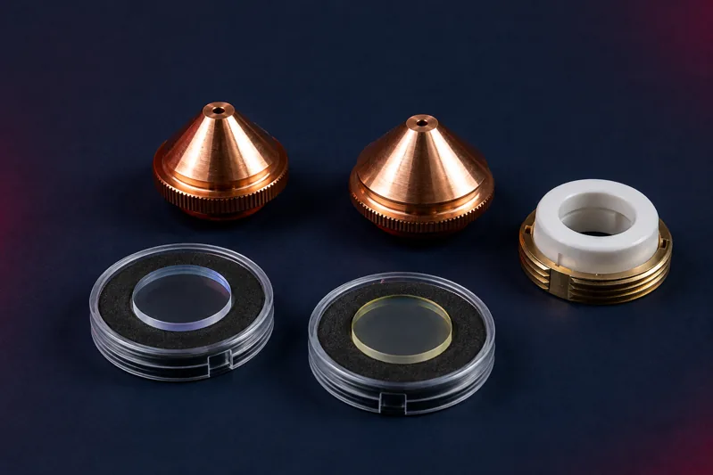
- Consumables. A worn or spattered nozzle, a contaminated protective lens, or a damaged ceramic ring will degrade cut quality in ways that look like a machine fault. This is the highest-yield thing to check first because it is quick and cheap. Our fiber laser consumables guide covers what to inspect and what "worn" actually looks like.
- The parameter profile in use. Confirm the job is running the profile for the material and thickness actually on the bed, not the one from the last job.
- The material itself. Mill scale, rust, oil, a different grade or a different supplier will change the cut without anything on the machine having moved.
- Assist gas. Check purity and, importantly, pressure at the nozzle rather than at the regulator.
Only once those are eliminated is it worth asking whether something is genuinely out of calibration. Adjusting a machine to compensate for a worn nozzle just moves the problem somewhere harder to find.
Two categories, and knowing which you are in
Calibration on a fiber laser splits cleanly into two groups, and conflating them is how shops either waste money or damage machines.
Operator-level work is routine, needs no specialist instruments, and should be part of normal shop practice: focus verification, nozzle centring, height sensor calibration, kerf offset, gas pressure. This is the category that actually drifts week to week.
Service-level work needs measuring equipment and training that no fab shop is going to buy for its own use: linear positioning accuracy over full travel, squareness compensation held in the control, backlash and drive tuning, anything inside the cutting head's beam path. A laser interferometer costs considerably more than the service visit that uses one.
You will see generic calibration guidance recommending things like ballbar testing. That is a machining-centre technique built around circular interpolation on a mill, and it is not how flat-sheet laser geometry is normally verified. Be careful about applying machining-centre metrology advice to a laser cutter without asking whether it transfers.
What to calibrate in-house
Focus position
Focus is the single most consequential setting on a laser cutter, and the one that most rewards attention. Focal position relative to the material surface changes with material and thickness, and a head that has been serviced, knocked, or simply run for months can drift from what the profile assumes.
Symptoms of focus being wrong include a rough or tapered edge, dross that will not tune out with gas changes, and pierces that take longer than they should or fail outright on thicker plate.
The standard verification is a focus ramp: cut a short line or series of features while stepping the focus offset across a range, then inspect where the kerf is narrowest and the edge is cleanest. That tells you where true focus sits relative to what the machine thinks. Every control handles the procedure differently, so use the routine documented for your machine rather than a generic one.
Nozzle centring
The beam has to exit through the centre of the nozzle orifice. When it does not, the assist gas comes out asymmetrically around the beam, and the cut becomes directional.
That directionality is the tell worth knowing: if edge quality or dross changes depending on which way the head is travelling, suspect nozzle centring before you suspect machine geometry. A square that has one clean side and one dross-heavy side is describing a concentricity problem, not a squareness problem.
Centring should be checked after any nozzle change, after head service, and always after a collision. The traditional check involves firing the beam through a marker over the nozzle to see where it lands relative to the orifice — but any procedure that fires the beam outside a normal cutting cycle has to follow your machine's documented method with the correct eyewear. See the safety note at the end of this article.
Capacitive height sensor
The cutting head follows the sheet by sensing capacitance between the nozzle and the material, and that relationship is not the same for every material. Aluminium and copper behave differently from mild steel, and a sensor calibrated on one will not track the other correctly.
Symptoms are hard to miss: the head crashing or diving, standoff varying across the sheet, or focus that is correct in one area and wrong in another. Recalibrate after nozzle changes and when moving between materials that behave differently — this is routine, not exceptional.
Kerf compensation
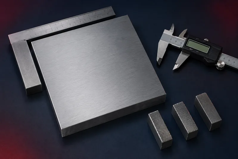
If parts come off consistently oversize or undersize by roughly the same amount, and the geometry is otherwise sound, that is a kerf offset problem rather than a calibration problem in the machine-geometry sense. It is one of the easiest things to verify: cut a test coupon with known nominal dimensions, measure it, and compare.
Kerf width varies with material, thickness, power and gas, which is why a single global offset rarely serves every job. Our guide to laser cutting kerf covers how it varies and how to compensate for it in the part geometry.
Assist gas pressure at the nozzle
Regulator pressure and nozzle pressure are not the same number. Line length, fittings, restrictions and a partially blocked nozzle all take their share, and the gap widens as the system ages. This is cheap to check and routinely overlooked, and a pressure shortfall at the nozzle will convincingly imitate a cutting parameter problem.
Cut a square of reasonable size and inspect all four edges. Uniform quality with the part off-size points at kerf compensation. Quality that changes with direction of travel points at nozzle centring. Unequal diagonals point at machine squareness — and that one is a service call, not a shop adjustment.
The geometry check you can run yourself
You do not need instruments to find out whether machine geometry is worth investigating. Cut a large square or rectangle — as large as the sheet and your measuring equipment sensibly allow — and measure both diagonals.
Equal diagonals mean the axes are square to each other. Unequal diagonals mean they are not, and the size of the difference tells you how urgent it is. Measuring a long dimension in both X and Y gives you a similar read on scaling.
What this test does is tell you whether to make the call. It does not tell you how to fix it, and this is the point to stop. Squareness and positioning compensation live in the machine control, adjusting them is not guesswork, and a shop that starts entering correction values to chase a symptom usually ends up further from true than it started. Record what you measured and hand that to your service technician — arriving with numbers makes the visit shorter and cheaper.
What genuinely needs a technician
- Linear positioning accuracy across full axis travel, which needs interferometry
- Squareness and pitch compensation values held in the control
- Backlash measurement and drive tuning
- Anything inside the cutting head's beam path
- Any diagnosis following a significant collision, where more than one thing has usually moved
The economics here are straightforward. The instruments cost more than the service calls, they need calibration themselves, and the skill is in interpreting the results rather than collecting them. Rise Tek services the machines we supply and a good deal that we did not — if you are unsure which side of the line a problem falls on, talk to our service team before you start adjusting things.
How often: trigger-based beats calendar-based
A fixed monthly calibration ritual tends to be either wasted effort or too late. Events are the better trigger:
- After any collision. Non-negotiable. Nozzle centring and height calibration at minimum, and a squareness check if the impact was significant.
- After head service, or lens and nozzle replacement. Nozzle centring and height sensor calibration.
- When switching to a materially different material. Height sensor calibration.
- When cut quality changes. Investigate in the order at the top of this article rather than adjusting first.
- At your scheduled service interval. The full geometry and positioning check, done properly with instruments.
The routine daily and weekly upkeep that keeps all of this stable sits alongside calibration rather than inside it — our fiber laser maintenance and safety guide covers that side.
Write it down
A calibration log converts "the machine has been cutting badly lately" into something diagnosable. What was adjusted, when, what the test coupon measured before and after, which consumables were changed. It costs a couple of minutes and it is the difference between a technician diagnosing from evidence and diagnosing from scratch.
If you work to a quality system, you already need this. If you do not, it is still the cheapest diagnostic tool in the building.
A safety note on beam procedures
Any procedure that fires the beam outside a normal enclosed cutting cycle deserves more caution than it usually gets. The fiber laser wavelength is invisible, so there is no blink reflex to protect you, and the real hazard in an open procedure is reflection off metal rather than the direct beam.
Follow the procedure documented for your machine, use eyewear rated for that specific wavelength — eyewear for a different laser type offers no protection — and do not defeat interlocks to get a better look at what is happening. If a procedure seems to require bypassing a safety system, that is the point to call service instead.