01 · Define the work
Identify material, dimensions, incoming condition and the surfaces to be processed.
A CANADIAN BRAND · POLAR FINISHING EQUIPMENT
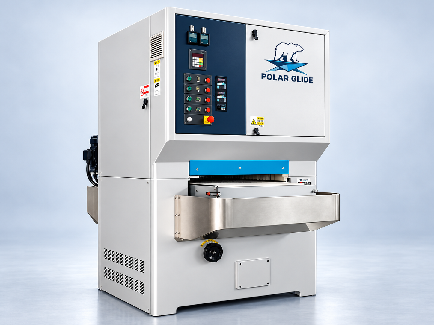
Light-duty metal sanding
A focused starting point for lighter sanding work. Select the configuration around your parts and target finish.
Branding illustration. Final machine configuration and appearance confirmed with your quotation.
Identify material, dimensions, incoming condition and the surfaces to be processed.
Agree on appearance and inspection requirements before evaluating representative samples.
Document the selected machine, tooling, extraction, site requirements and commissioning responsibilities in the offer.
A focused starting point for lighter sanding work. Review your material, incoming surface and target finish to define the right configuration.
Explore Glide ↗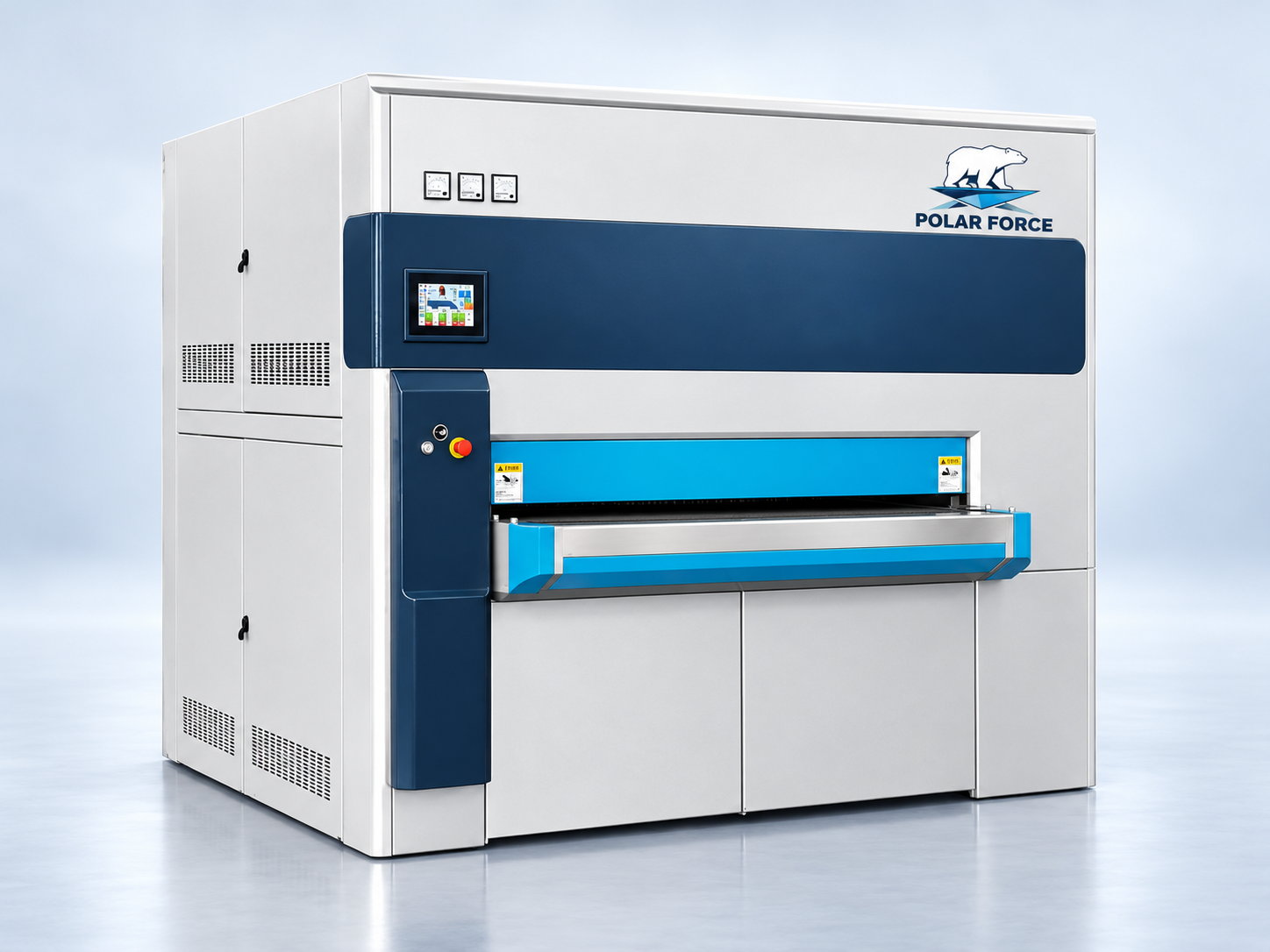
For shops evaluating a heavier-duty sanding platform. Match the machine configuration to your parts and production requirements.
Explore Force ↗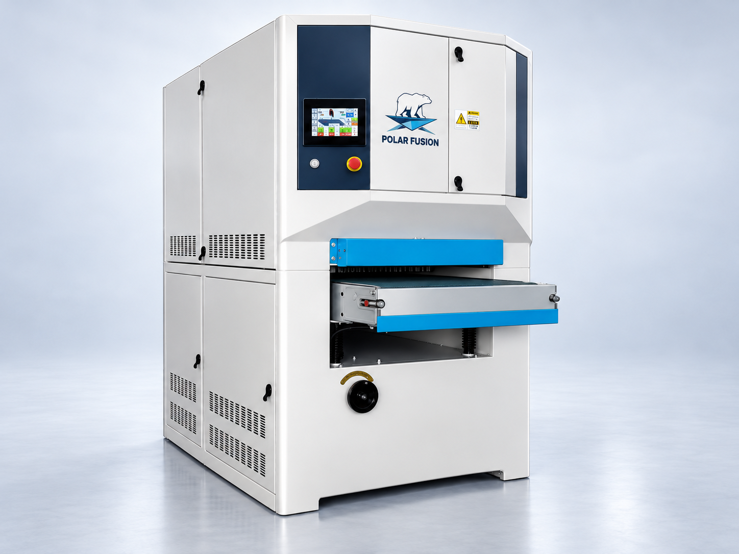
A combination-head platform for reviewing sanding and finishing stages together. Define the process around your required result.
Explore Fusion ↗Send material grade, width, thickness, length, flatness and incoming surface condition. Identify the faces to process and any protective film.
Provide a reference finish and representative parts. Agree on grain direction, appearance, measurement method and acceptable marking before ordering.
Confirm working width, head arrangement, abrasives, feed range, electrical supply, extraction and any wet-processing system. Document guarding, local electrical approval, installation and training scope.
Specifications, accessory inclusion, pricing and delivery are confirmed in the written offer. Processing results depend on the selected configuration, material, abrasives and incoming part condition.
Configuration-specific values from the supplied light-duty technical sheet. Confirm the final ordered configuration and electrical requirements with Rise Tek.
On smaller screens, swipe the table to see all columns.
| Technical item | Catalogue reference | Selection note |
|---|---|---|
| Working width | 1,300 mm | Reference twin-roller configuration. |
| Head arrangement | A–A; two rubber contact rollers | Two abrasive-belt roller stations. |
| First roller | 150 mm diameter; 30 HP | Sheet lists hardness 55; hardness scale is not specified. |
| Second roller | 150 mm diameter; 25 HP | Sheet lists hardness 50; hardness scale is not specified. |
| Roller motor inverter range | 30–70 Hz | Electrical frequency setting, not a stated belt surface speed. |
| Conveyor motor | 2 HP; inverter 12–75 Hz | Confirm feed speed in m/min for your quotation. |
| Conveyor belt size | 1,300 × 3,000 mm | Conveyor belt dimensions, not abrasive-belt dimensions. |
| Tracking | Electronic-eye tracking | Verify the delivered control arrangement. |
| Table support | Four lifting poles | Motorized table hoist with digital readout. |
| Wet processing | Wet-system option listed | Confirm pump, filter, circulation and inclusion. |
| Electrical reference | 220 V / 60 Hz | Do not assume compatibility with the site supply; confirm phase and approved installation scope. |
The metal-sander catalogue lists conveyor tracking, a quick-release sanding-belt mechanism and a main-motor load meter. The Force technical sheet also describes abrasive-belt oscillation and tensioning.
Four-point table support, powered thickness adjustment and infeed/outfeed support are documented on the referenced configurations. Confirm minimum part size, support length and vacuum holding separately.
The Force reference describes a front touch screen, motor overload protection, emergency stops and shutdown conditions for belt or air-supply faults. Site electrical approval and the final guarding package must be confirmed for the supplied machine.
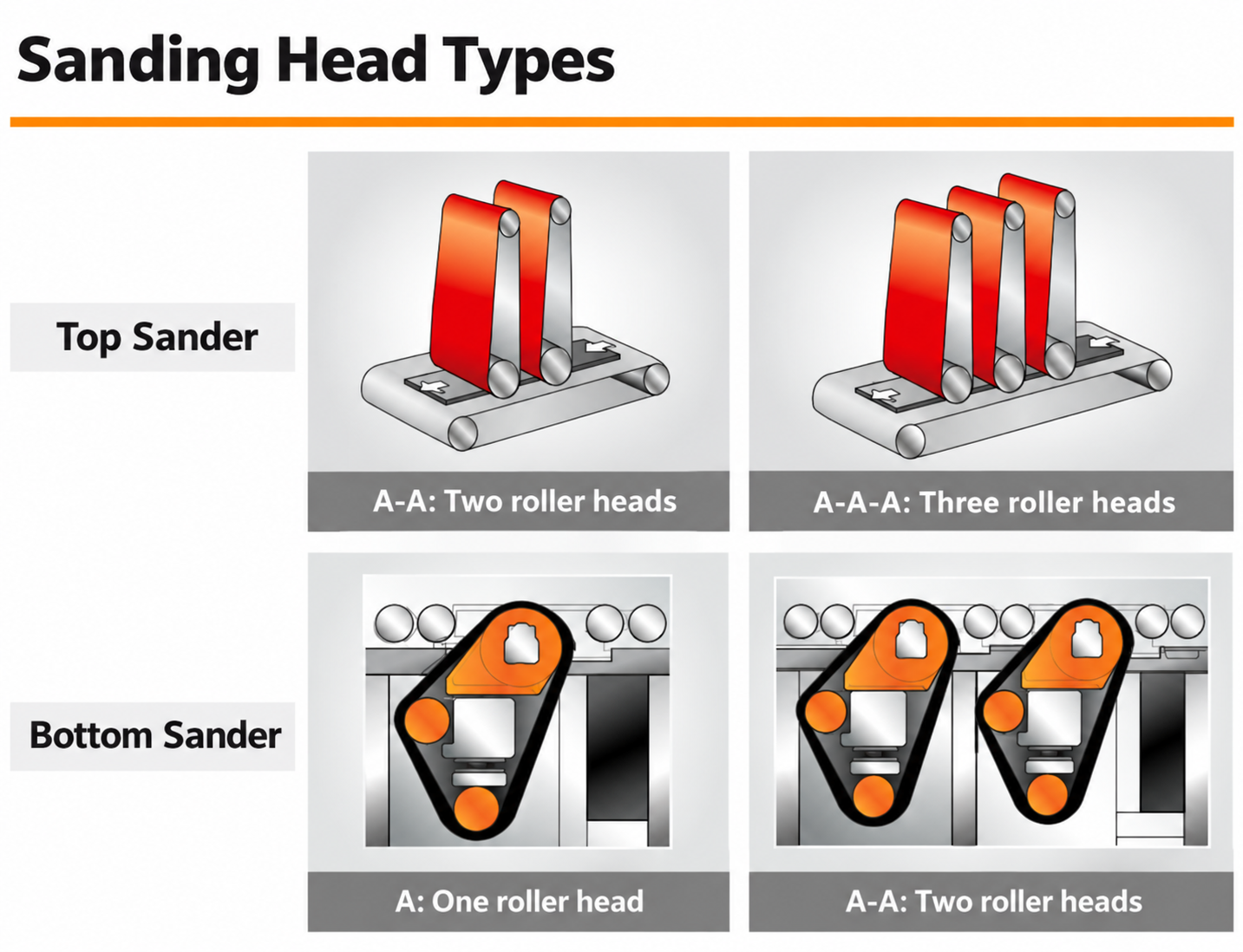
The metal-sander catalogue illustrates top sanding with two or three roller heads and bottom sanding with one or two roller heads. These are alternative machine arrangements; a top-sanding machine does not automatically include bottom sanding.
A roller head uses an abrasive belt over a contact roller. Brush or disc stages are selected separately around edge treatment, surface appearance and part geometry. For two-face work, confirm whether the proposed process uses separate machines, a dedicated line or part reversal.
Discuss your head configuration ↗Original catalogue tooling photographs. These are selection options, not a statement that every brush is included or fits every Polar model.
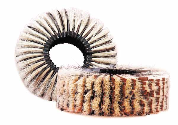
Abrasive flaps with supporting fibres. Specify the abrasive, grit and required surface treatment.
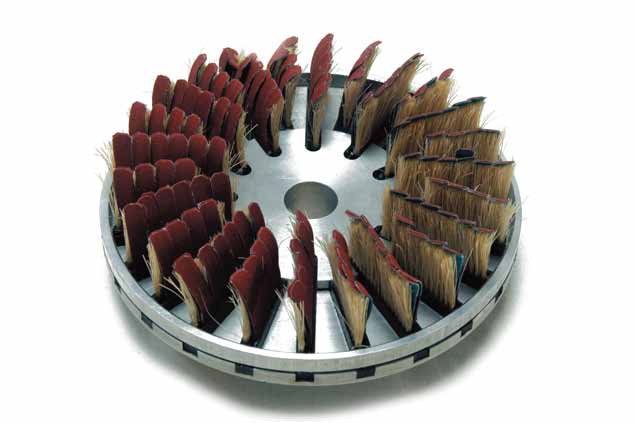
A disc-format tool for a compatible brushing station. Confirm part holding and the desired edge result.
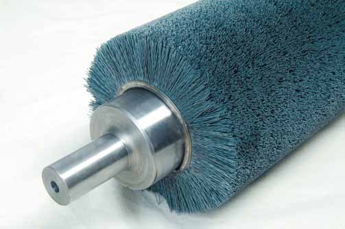
A catalogue-listed brush format. Confirm filament type and compatibility with the work material.
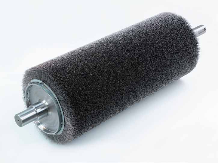
Select wire type and material compatibility; agree on acceptable marking and contamination controls.
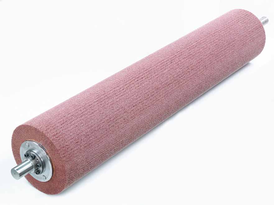
A non-woven abrasive format for evaluating blending and finishing requirements.
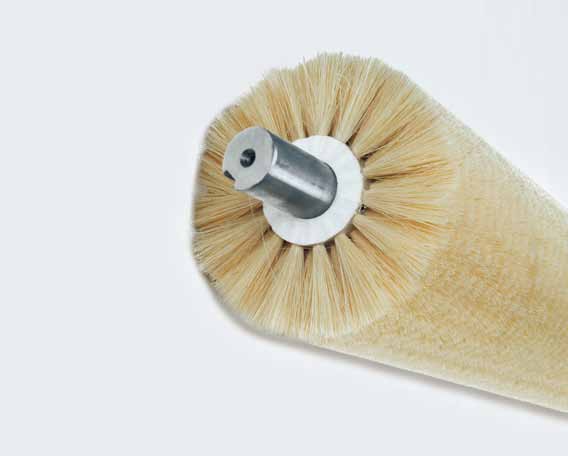
A fibre-bristle format. Confirm its cleaning or finishing role in the selected machine.
Bring your material, part dimensions, incoming condition and target finish. We’ll use those details to discuss the machine and quotation scope.