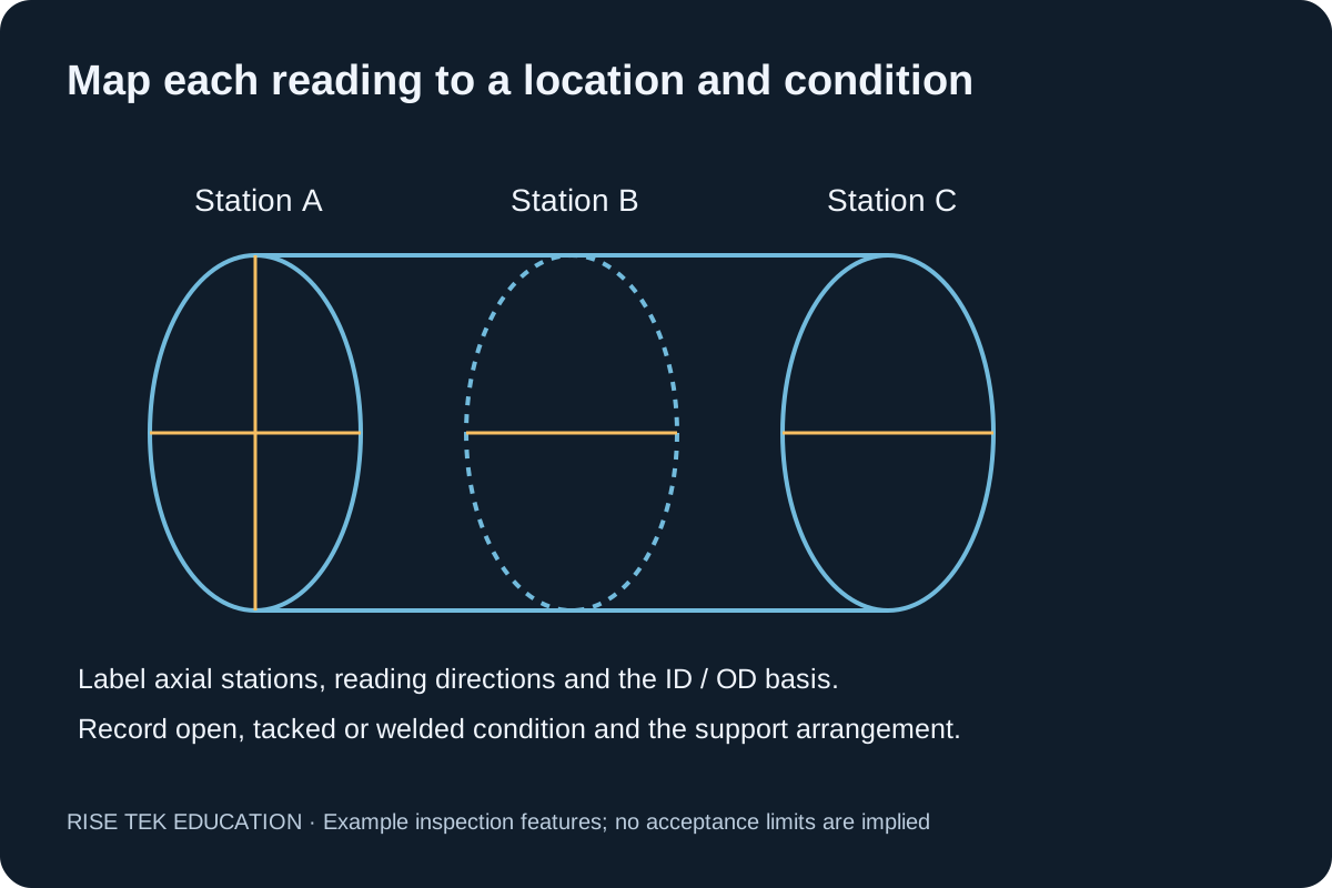
A plate-roll first-article inspection record should connect every result to a drawing requirement, measurement location and inspection condition. Record diameter, roundness, end flats and seam mismatch separately. A shell that meets one requirement may still fail another, and a single diameter reading is not a complete shape assessment.
This guide gives Canadian fabricators a practical structure for recording the first part after setup or an agreed process change. It complements our supplier sample-acceptance guide: that guide defines the trial scope, while this one organizes the dimensional evidence. The drawing, purchase specification and approved inspection plan determine the actual tolerances and methods.
1. Establish the inspection condition and location map
Record the part number, drawing revision, material identity, actual thickness, machine configuration, inspector and date. Identify the process stage: as rolled and open, temporarily restrained, tacked, welded or subsequently corrected. Record the supports or fixtures and whether any force is holding the shell into shape.
Do not compare a freely supported open shell with a restrained or welded shell without identifying the difference. The inspection plan must state the condition in which each requirement applies. See the springback guide and supports and handling guide for related planning questions.
Mark axial stations and reading directions on a sketch. For example, A, B and C can identify two end regions and an intermediate section, but their actual offsets and the number of stations must come from the agreed plan. Keep the seam orientation visible on that sketch. The illustration is a location-map example, not a required sampling density.
2. Record diameter without hiding local differences
Identify inside or outside diameter, nominal size, tolerance, units and the measurement method. Record each required direction at each station instead of entering only an average. Differences between stations may indicate axial shape variation that one middle reading would miss.
Use equipment appropriate to the shell size, access, tolerance and specified measurement definition. Record the instrument identity and verification or calibration status. Contact force, alignment, support and environmental conditions may matter; include them where the method requires. Instrument resolution alone does not establish that a method is suitable.
A circumference-based diameter describes an equivalent diameter from the measured perimeter. It does not by itself establish local diameter or roundness. Likewise, a local radius template is a local contour check, not automatic proof that the entire shell meets its diameter requirement. Use these methods only for the acceptance purpose agreed.
| Characteristic | Required definition | Record |
|---|---|---|
| Diameter | ID or OD; nominal and tolerance; stations and directions | Individual readings with method and units |
| Roundness or specified out-of-roundness | Exact characteristic, calculation/evaluation method and section | Result and referenced measurement data |
| End flats | Edge identification; length or profile criterion; reference method | Each specified edge/location result |
| Seam gap | Edge separation reference, locations and inspection stage | Gap results separately from mismatch |
| Seam mismatch | Reference surfaces and permitted step at the seam | Mismatch results and any restraint used |
3. Define roundness rather than assuming a formula
Two-point diameter readings are useful for an agreed shop check, but they do not capture every possible profile deviation. A difference between the largest and smallest sampled diameters is a diameter spread; do not automatically label it a geometric roundness result.
When the drawing specifies geometric roundness, use the applicable profile measurement and evaluation method accepted by the responsible reviewer. When a fabrication specification instead defines an out-of-roundness or ovality calculation, record that definition, its units and any denominator explicitly. These terms and formulas should not be substituted for each other.
Keep the raw readings or referenced scan/profile report with the result. Do not impose an arbitrary percentage on every shell. If the required method or tolerance is missing, leave the disposition on hold until it is agreed; a visually circular shell is not a substitute for the required measurement.
4. Inspect both end flats and seam geometry
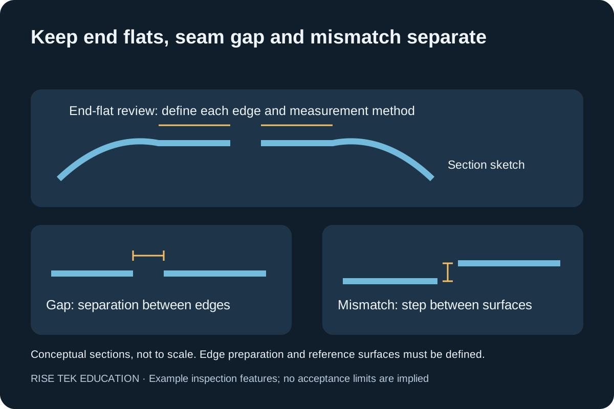
End flats are the residual straight portions near the plate ends that become the longitudinal seam edges. Identify both edges and agree how the straight portion or departure from the intended contour is assessed. Record the locations across the shell width, the reference and the permitted result. Do not assume a universal end-flat length based on thickness or roll count.
A template or other profile method may be appropriate if its contour, placement and acceptance rule are defined. Document what is actually checked rather than reporting an undefined “flat” value. Our pre-bending capacity guide explains why end forming must be considered separately from main rolling capacity.
Seam gap is separation between edges; seam mismatch is the step or offset between the specified adjacent surfaces. Measure and record them separately at the agreed locations. Identify the reference surfaces, particularly where plate thickness or edge preparation differs. A small gap does not prove low mismatch, and aligning one end does not establish the condition along the whole seam.
Record any fit-up restraint and whether the measurement is before or after tacking or welding. The first-article record does not authorize a welding procedure or establish code compliance. Any project-specific fabrication requirements need their own approved review.
5. Close the record with a clear disposition
For every characteristic, enter the requirement, actual result and pass, fail or hold status. Reference photographs, profile data and instrument records as needed. Keep appearance acceptance separate using the stainless surface-finish and marking guide.
If correction is authorized, preserve the original result and add the corrective action and reinspection result. Check affected characteristics again rather than replacing the failed reading with a new number. Record who approved the final disposition and any remaining restrictions.
One accepted first article is evidence for that part and inspection condition. It does not establish long-run capability or guarantee every later shell. Agree when subsequent checks or a new first article are needed after changes to material, setup, tooling or other relevant conditions.
Download the blank plate-roll first-article inspection record. Its example stations and rows must be adapted to the drawing; it contains no default tolerances or automatic pass/fail formulas. Send your drawing and inspection requirements to request a RollTek application review.
Check these out
Send your drawing for a model-specific application review.
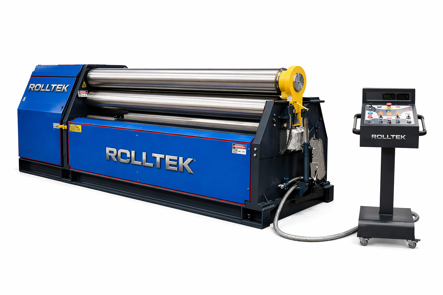
RollTek VERTEX 3-roll plate rolls
Review the selected model’s rolling and pre-bending capability against your drawing. Agree end-flat, diameter and seam inspection requirements for the trial.
Explore machines →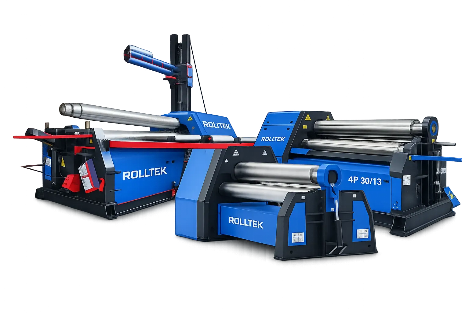
RollTek TITAN 4-roll plate rolls
Discuss the configuration, supports and inspection condition for representative shells. Four rolls alone do not guarantee roundness or seam acceptance.
Explore machines →Frequently asked questions
Is one diameter reading enough for first-article inspection?
Use the stations and directions required by the approved plan. One reading does not establish the shape along or around the shell, and it does not replace a specified roundness assessment.
Is maximum diameter minus minimum diameter the same as roundness?
Not automatically. It is a diameter spread from the readings taken. Use the specified geometric roundness evaluation or the explicitly agreed fabrication out-of-roundness calculation.
What is the difference between seam gap and seam mismatch?
Gap is separation between the seam edges. Mismatch is the step or offset between the specified adjacent surfaces. Record both at the agreed locations and process stage.
What end-flat length is acceptable on a rolled shell?
The drawing and approved inspection plan must define it, including the reference and method. There is no universal acceptable length for every material, thickness and application.
Does an accepted first article prove production capability?
No. It records the inspected part under stated conditions. Agree subsequent inspection and repeatability requirements separately, including when process changes require another first article.